
Introduction
To any novice new to the hobby, the setting up of your first trainer model can be a confusing business!
Nowadays, your first trainer is likely to be an electric model although some do start with IC (Internal Combustion engine) ARTF (Almost Ready to Fly) kit like the Irvine Tutor 40. A good electric model to get you going would be the Xfly Glastar, Hobbyking Tundra or the Max Thrust RIOT.
Having experienced quite a few new members arriving at the flying site with their pristine model, only to be told that it cannot be flown since it requires further ‘surgery’, I had the idea of putting some information together to solve some of the more common problems. Hence this page!
It might be a good idea to print this page off. If you follow these instructions below to the letter, I can guarantee that your pride and joy will fly straight off the building board with very little re-work.
Flying Modes
You will find that which mode to use will be purely down to personal preference. Note that the new digital transmitters are very good in that the chosen mode can be changed electronically very easily, although you must switch the tx stick operation mechanically (i.e. move the friction ratchet to the appropriate throttle stick – don’t worry, we can do that for you very easily and at no extra charge!!).
Non digital radio sets will have the mode ‘hard-wired’, so if you are buying one of these sets, be absolutely sure of the mode it is set up for and it is the mode you want! (FYI: most EBay advertisers do not specify the mode – always ask the seller!!)
Mode 1
Left Stick – Rudder and Elevator, Right Stick – Aileron and Throttle
Mode 2
Left Stick – Rudder and Throttle, Right Stick – Aileron and Elevator
Transmitter Set Up
Stick Length
Most transmitters (or tx) allow you to adjust the length of the two main control sticks.
It is recommended that the sticks should be adjusted so that the stick length is approximately 35mm from the tx gimbal.
To adjust the length, loosen the locking nut, turn the knurled stick end in or out as required to the desired length, then tighten the locking nut again.
If your transmitter has dual rates, set the variable throw adjustment screws to 50% (i.e. when rates are switched in, the aileron and elevator control surfaces are reduced in movement by half).
Radio Gear Installation and Set Up
Battery and Receiver
Ensure that both battery and receiver are wrapped in foam and wedged securely in the fuselage. The best stuff is the packing material that comes with electrical goods.
It is also preferrable to position the battery as far forward as possible to aid the balance (centre of gravity) of the model – it also has the added advantage that the heavy battery does not smash its way through the delicate receiver in a crash!
If you fit the switch through the fuselage sides, fit it on the OPPOSITE side to the exhaust, so that it does not get covered in oil. Better still, install it inside the fuselage and make up a wire pull/push rod which is accessible from the fuselage side, in order to switch the radio on and off.
Trim Levers
The trim levers are the small slider controls at the side and bottom of each stick gimbal on the transmitter. Digital Tx’s make a ‘beep’ noise every time you adjust the trim (usually in 5% increments). NOTE: with a digital tx you cannot tell where the trims are by just looking at them!! You have to see the what the digital read out is telling you.
Before attempting any radio installation, always ensure that the trim levers are positioned as below:
Function | Position |
Aileron | Central (or 0%) |
Elevator | Central (or 0%) |
Rudder | Central (or 0%) |
Throttle | Fully Forward (or -80%) |
Position of Servo Arms
Always fit the servo arms as below, when the trim levers are set up as above – this is VERY IMPORTANT to ensure that you get EQUAL control surface movement.
Function | Position |
Aileron | 90 degrees to servo casing with tx stick and trim central |
Elevator | 90 degrees to servo casing with tx stick and trim central |
Rudder | 90 degrees to servo casing with tx stick and trim central |
Throttle | 45 degrees to servo casing when fully open (tx stick and trim fully forward) |
Note that you may have to experiment by rotating the fitting of the servo arms to achieve the above, since the splines on the servo arms may be slightly off centre.
Correct setting with servo at 90 degrees 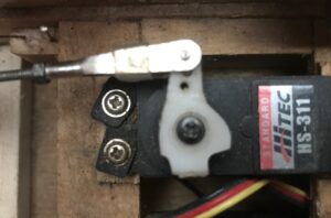
Incorrect Setting with Servo not at 90 degrees 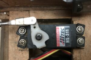
Ensure that all the other unused arms on each servo arm are sawn/trimmed off to ensure that they do not foul the pushrods at maximum deflection.
Servo Arm
NOTE: The closer IN the hole used, the LESS movement achieved, the further OUT the hole used, the MORE movement achieved – see diagram below!
Less movement using inner hole and more load on servo 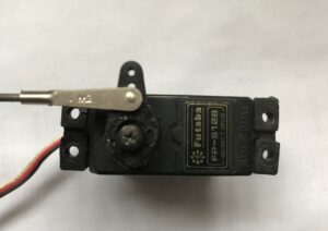
More movement using outer hole and less load on servo 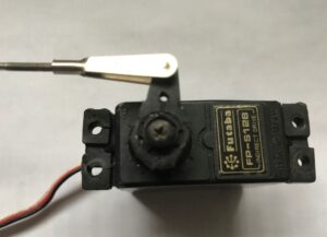
Position of Control Surfaces
Always make up the push-rods to the correct length so that the aileron, elevator and rudder control surfaces are at NEUTRAL (i.e. have NO deflection), and that the quick links are screwed onto the push rod ends with AT LEAST 8mm of thread used up.
Note that it is a very good idea to have the radio switched on (both transmitter and receiver of course!) when making up and fitting the push-rods, to ensure that the servo arms are always positioned centrally.
Position of Quick Link – Control Surfaces
Always fit the horns on the elevator and rudder so that the HOLES line up with the HINGE LINE.
NOTE: The further OUT the hole used, the LESS movement achieved, the closer IN the hole used, the MORE movement achieved – see diagram below!
Control Horn
More movement achieved by using inner hole but more load on servo 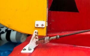
Less movement achieved by using outer hole but less load on servo 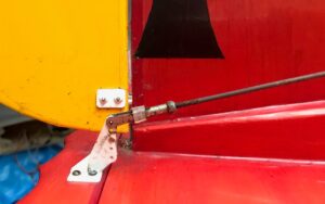
For additional safety and security, cut 6mm lengths of fuel tubing and slide them over the quick links before they are screwed to the push-rod ends. Once the quick link is attached, slide the fuel tubing as far up the quick link as it will go, thus stopping the quick link from coming apart in flight! !
Control Throws
As a good starting point, set the control throws as below (measured as the distance each surface moves from neutral).
Function | Movement |
Aileron | 15mm |
Elevator | 15mm |
Rudder | 35mm |
These should make the trainer crisp on the controls, but if necessary, they can be adjusted later to suit the individual preferences.
Correct Control Movements
These are viewed from the REAR of the model.
Function | Stick Movement | Control Surface Movement |
Aileron | Left | Left Aileron UP, Right Aileron DOWN |
Aileron | Right | Right Aileron UP, Left Aileron DOWN |
Elevator | Back (towards your body) | Elevator UP |
Elevator | Forward (away from your body) | Elevator DOWN |
Rudder | Left | Rudder LEFT |
Rudder | Right | Rudder RIGHT |
Throttle | Forward (away from your body) | Throttle Action – OPEN THROTTLE |
Throttle | Back (towards your body) | Throttle Action – CLOSE THROTTLE |
NOTE: it is very important to set the throttle trim correctly.
On an electric model make sure the throttle trim is set right down as sometimes it may be too high for the model to bind to the Transmitter.
On IC initial set-up, fully forward trim is used, so that a reliable and slow tick-over can be achieved by small trim adjustments, and also so that the engine can be STOPPED immediately, by winding the trim FULLY BACK.
NOTE: the Futaba 6EX has a very good facility which replicates the above safety feature- if you quickly flick the trainer switch twice, the throttle will close immediately. The later versions of this radio set have a throttle close button on the front panel, which does exactly the same thing. Spectrum radio gear also has the facility.
Fuel Tank
This can cause a great deal of confusion but is quite simple. Most tanks have THREE pipes. They are secured in place with a rubber bung through the access hole in the tank, which has a screw to compress the rubber to provide a leak free joint.
1. The carburettor feed pipe from inside the tank will have a ‘clunk’ attached to the end of the internal tubing. This will ensure that whichever way up the model is when flying, the clunk will always fall by gravity to the bottom of the tank, where the fuel is, and therefore always supply fuel. Simple eh!! (It is known as a clunk after the clunking noise when you shake the tank or model when empty!!) A good tip is to hold up the tank to a strong light, invert the tank and see that the clunk drops cleanly. If the internal tubing is too long, the clunk will not move around inside the tank smoothly! This pipe must obviously be connected to the fuel nipple on the carburettor via the external fuel tubing.
2. The next pipe is the exhaust pressure pipe, which is connected to the nipple on the exhaust. This has the effect of giving the tank some positive pressure when the engine is running, by feeding the exhaust gas into the tank, and helps the engine to run a little better. (Note that the exhaust feed is NOT imperative for the engine to run – it will still run without!)
3. The last pipe is simply the filler pipe used to fill the tank before flight. It is usually sealed with a screw which is removed to fill the tank and replaced when full. This pipe is optional – you can fill the tank by removing the carburettor feed pipe from the nipple, connect your fuel supply, fill the tank and re-attach the pipe to the carburettor when the tank is full.
The exhaust pressure and filler tubes should be bent UPWARDS to touch the top of the tank, so that when you fill the tank, it actually fills to the top! Think about it, if the filler pipe is just straight through the rubber bung, you will not completely fill the tank! Hopefully the cross section diagram of a tank will explain things – see below.
If you have assembled your tank correctly, when the tank is filled completely, fuel will come through the exhaust pressure feed pipe, which is a very simple way of telling when to stop pumping!!
/————top of tank———————-
|. . . . . . . ./ . . . . . . . . . . . . . . . Fill level
|o|____/ <————————– Exhaust Pressure Feed (+ Filler pipe if fitted) cranked upwards
|o|
|o|—- <———————— Carburettor Feed pipe with clunk attached to tube
|
\————bottom of tank——————
Kev’s Top Tip No. 1! If you see bubbles coming through the feed pipe when the engine is running, then there will be a small pin hole somewhere along the feed pipe, allowing air to be sucked in. Not good for consistent engine running!!
Kev’s Top Tip No. 2! If you have problems with your engine after a heavy ‘arrival’ (or mild crash!), then the clunk can be wedged at the front of the tank, thereby kinking the flexible pipe and not providing enough fuel flow. Giving the plane a good shake usually frees it up!!
Kev’s Top Tip No. 3! If you don’t fit a tank access hatch or have easy access to the tank through the fuselage, I can bet you will have tank problems!! The last thing you want is to have to dismantle half the plane at the patch, in order to fix any problem(s)!
Engine
The setting up of the carburettor sometimes baffles newcomers to the sport.
The carburettor almost always has TWO needles that control the mixture. The mixture needs to be set according to the conditions of the day for a) optimum power and b) smooth idle and pickup when the throttle is opened.
1.The MAIN needle is the large knurled knob either directly protruding from the carburettor itself, or the remote needle valve assembly to the rear of the cylinder block. (The remote assembly is a recent innovation for safety reasons, since the main needle is further away from the propellor – fingers and props turning at over 15,000 are not compatible – I have the scars to prove it!).
2.The SLOW RUNNING needle is EITHER the small screw fitted into the barrel the OPPOSITE side of the main needle (fuel bleed type), OR is a small, spring loaded screw protruding from the body of the carburettor (air bleed type). (Don’t get confused with the throttle barrel stop screw – which has nothing to do with mixture control!).
The main needle controls the mixture when the throttle barrel is MORE THAN 2/3 open, while the slow running needle controls the mixture at idle up to 2/3 open, when the main needle kicks in.
MAIN NEEDLE – screw OUT to RICHEN, screw IN to WEAKEN.
SLOW RUNNING NEEDLE (fuel bleed type) – screw OUT to RICHEN, screw IN to WEAKEN.
SLOW RUNNING NEEDLE (air bleed type) – screw IN to RICHEN, screw OUT to WEAKEN.
Adjusting the carb should be done in two steps. Securely restrain the model before following the instructions below!
Firstly, start the motor and open the throttle fully. Adjust the MAIN needle until the exhaust note is a crisp ‘two-stroke’ noise. Check that the motor runs at this setting with the plane angled upwards at 45 degrees. If you weaken the mixture too much, the engine will overheat and stop – richen the main needle and start the engine again, and repeat the above.
Once you are happy with the main needle setting, close the throttle to tickover. Now open the throttle quickly – if the motor responds crisply, then the slow running needle is OK. If it splutters before picking up, weaken the slow running needle. If it stops, richen the slow running needle. Note that only VERY small adjustments should be done with the slow running needle (say 1/4 turns at most).
Usually, once the slow running needle is set, it may only occasionally need adjusting. The main needle often needs SLIGHT adjustment before flight, according to the conditions of the day!
Control Surface Security
I have never had a control surface come adrift if you take the following precautions!
Hinges – for extra security, you cannot beat pinning all hinges (aileron, elevator and rudder) with a short length of cocktail stick. Cut cocktail sticks to the desired length, and drill a hole on each side of the hinge line with a 1/16th drill. NOTE this is best done from the UNDERSIDE, so that the cocktail stick pins do not show, and if you are careful and do not drill all the way through, they will hardly be seen. Put a small blob of white glue in the drilled holes, then tap in the length of cocktail stick. Those hinges will NEVER come adrift now!
Quicklinks – cut a 6mm length of fuel tubing and slide over the quicklink before screwing onto the pushrods. After you have attached the quicklink to the control horn, slide the fuel tubing up as far as it will go towards the horn, thus stopping the quicklink from coming apart. This trick is essential for the plastic quicklinks that are supplied with most ARTF kits……….!