Side/Down Thrust Angles
Thrust Angles.
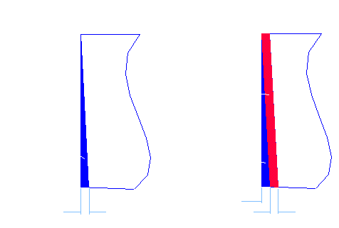
| One of the big construction problems with model aircraft and their engines is that, on most models, there is side and/or down thrust required. The engine usually points down and to the right. Depending on the model, this is usually about 1½° down and 2½° to the right. This causes a secondary problem because to ensure that the propellor spinner is on the thrust line of the model, the engine mounting must be positioned above and to the left (looking from above the model). The best way to set the side and down thrust is to angle the “firewall” (the fuselage former that the engine mounting attaches to). To achieve this, both fuselage sides must be cut to the down thrust angle and the right fuselage side only must be cut to allow for the right thrust angle. Complicated or what? For those of us with access to 3D CAD, this is no big deal. For those of us who found Maths as interesting and comprehensible as Relativity Theory, there has to be an easier way! Hopefully, this is it. A quick look at the model plan will let you know what the distance is from the rear of the propellor spinner to the firewall. Remember that you require a gap of about 3mm (1/8″) between the propellor spinner and the nose ring of the cowling. For the sake of calling this distance something, we’ll call it the Overall Length. Down ThrustWe’ll start with the Down Thrust angle. How much shorter does the bottom of the fuselage side have to be to get the correct down thrust angle and how far above the thrust axis does the engine mount have to be?
|
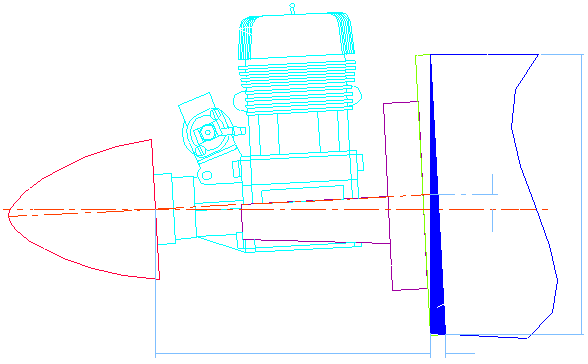
For the mathematically inclined, the Trim Length has a formula (inevitably!)….
Most calculators should be capable of this calculation (or use the Windows 95 calculator in Scientific Mode). As an example, for a Down Thrust Angle of 1.5° and a Firewall Height of 100mm (4″), the formula becomes:-
The Up Length is calculated similarly. This time the formula changes to:
For example, if the Overall Length from the Spinner to the Firewall is 125mm. (5″) and the Down Thrust Angle is 1.5°, the formula becomes:-
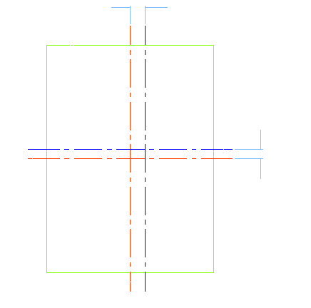
Side ThrustTo set the required Side Thrust, we have to trim a strip from the right hand fuselage side only and offset the engine mount to the left to compensate for this angle. These values can be calculated in a similar manner to the Down Thrust requirements. |
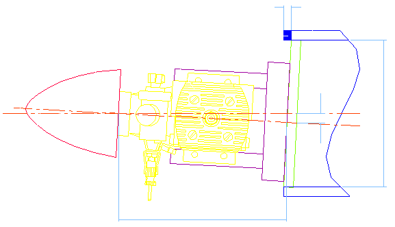
As with Down Thrust, there are formulae for calculating how much to trim from the right side fuselage and how far to offset the engine mount:-
Using the Overall Length (125mm. [5″]) in the example above with a Side Thrust Angle of 2° and Firewall Width of 75mm (3″), the formulae come out to:-
SummarySo what have we got and what does it mean? We have to angle both sides of the fuselage equally to give Down Thrust and raise the Engine Mount above the 0° line and these are dictated by the formulae:
We also have to trim a strip from the right hand fuselage side and offset the engine mount to the left and these are dictated by the formulae:
Since tan( Angle ) is just a value which varies with the angle, an easier method is to tabulate some common values for angles and re-write the formulae to:
|
| Thrust Angle Multipliers | |||||||
| 0.5° | 1.0° | 1.5° | 2.0° | 2.5° | 3.0° | 3.5° | 4.0° |
| 0.0087 | 0.0175 | 0.0262 | 0.0349 | 0.0437 | 0.0524 | 0.0612 | 0.0699 |
| Use the table above to find the multiplier for the required Down and Side Thrust Angles. The example we have used so far has an Overall Length of 125mm. (5″), Firewall Height of 100mm. (4″) and a Firewall Width of 75mm. (3″). The Down Thrust required is 1.5° and the Side Thrust is 2.0°. Looking up the table gives a Down Thrust Multiplier of 0.0262 and a Side Thrust Multiplier of 0.0349.
Now that the calculations have been done, the fuselage sides and firewall can be modified to generate the correct angles. |
